Description
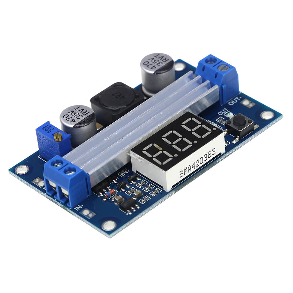
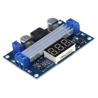
LTC1871 DC-DC Step Up Booster Converter 3.5-35V DC LED Power Supply Module.
1. LED power indicator.
2. Button to switch measurement of the input or output voltage, and LED indicates the current measurement of the input or output voltage; The nixie tube can be turned off by another button. Mentioned states are able to be memorized, is not lost even if the power is disconnected. (On-board marked “IN” LED is turned on, the nixie tube display input voltage value, “OUT” LED bright display is the output voltage value).
3. Special launch, the voltmeter calibration function, will never exist voltmeter inaccurate!
Voltmeter calibration method:
(1) Output voltage calibration steps
Step 1, adjust the right button so that “OUT” LED lighted, the voltmeter shows the value of output voltage; Press the right button for more than 2 seconds, release, voltmeter and “OUT” LED flashes in synchronization so that you enter the output voltage calibration mode.
Step 2, press the right button (normal speed), the voltage value is adding up a unit; Press the left button, minus a unit; Due to a unit is less than 0.1V, the minimum voltage display to 0.1V, so you need to continuously press 1-5 times to see the voltmeter change 0.1V, how many times voltmeter change 0.1V by pressing the key, depending on the current display voltage, the higher the voltage, the fewer the number of press.
Step 3, press the right button for more than 2 seconds, release, to exit the output voltage calibration mode. All parameters set to automatically power down to save.
(2) Input voltage calibration steps
Step 1, adjust the right button so that “IN” LED lighted, the voltmeter shows the value of input voltage; press the right button for more than 2 seconds, release, voltmeter and “IN” LED flashes in synchronization so that you enter the input voltage calibration mode.
Steps 2 and 3, consistent with the output voltage calibration method.
1.input voltage range:3~35VDC(Note: the input voltage is less than 4V, voltmeter failure)
2.input current:9A (max)
3.output voltage range:3.5~35VDC(please to ensure that output voltage above on input voltage)
4.output current: 6A (max)
5.output power: 75W (when the input and output voltages greater than 20V up to 128W)
6.conversion efficiency: 96.4% (max)
7.voltmeter range: 4 to 40V, error ±0.1V
8.short circuit protection: yes(limit current 14A). (Note: connected to high-power load, just switched on the impact of current very general meeting current limiting self-locking protection, it is recommended to be switched on firstly, and then access the load).
9.input reverse polarity protection: None (if required, high current diode in series with the input).
10.L x W x H = 67 * 43 * 12mm

